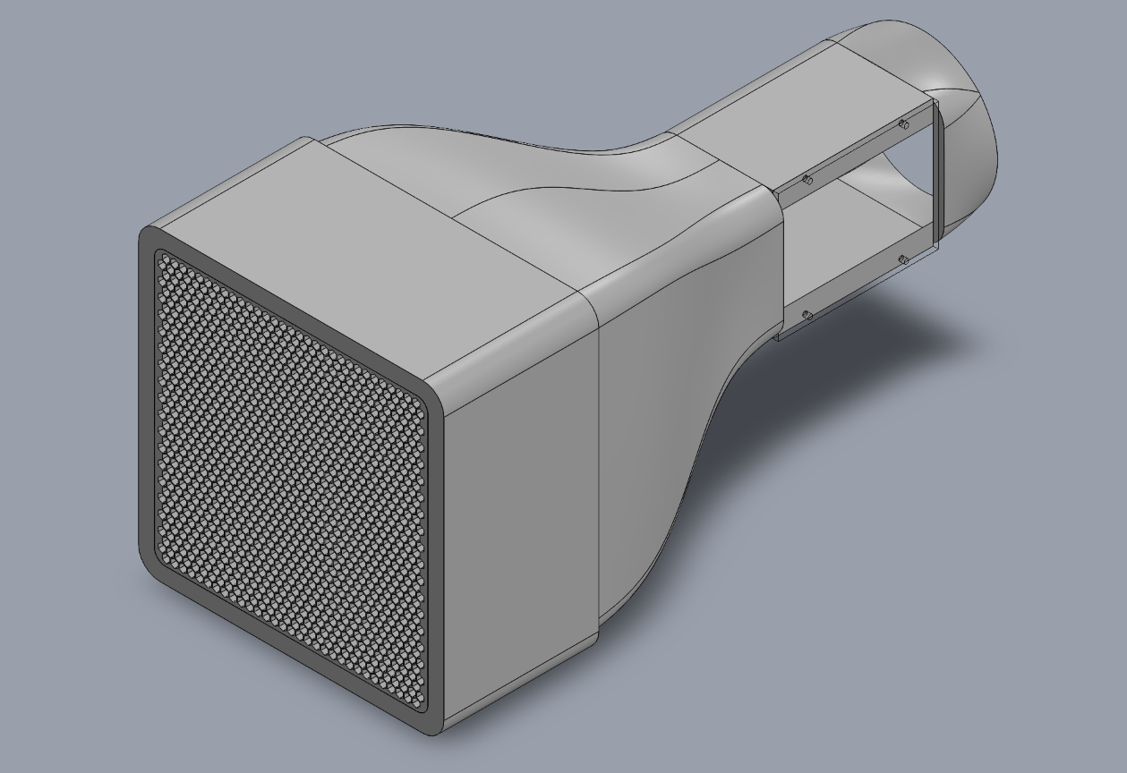
Full Assembly
Project Overview
The goal of this project was to design and manufacture a desktop wind tunnel capable of measuring lift and drag forces on various aerofoil profiles within a 100x100mm test section.
Project Objectives
- Uniform Airflow: Achieve consistent laminar flow at 15m/s using a polynomial contraction cone.
- Force Measurement: Develop a parallel-motion flexure linkage to isolate and measure forces.
- Manufacturability: Design components to be compatible with a 256x256x256mm 3D printer build volume
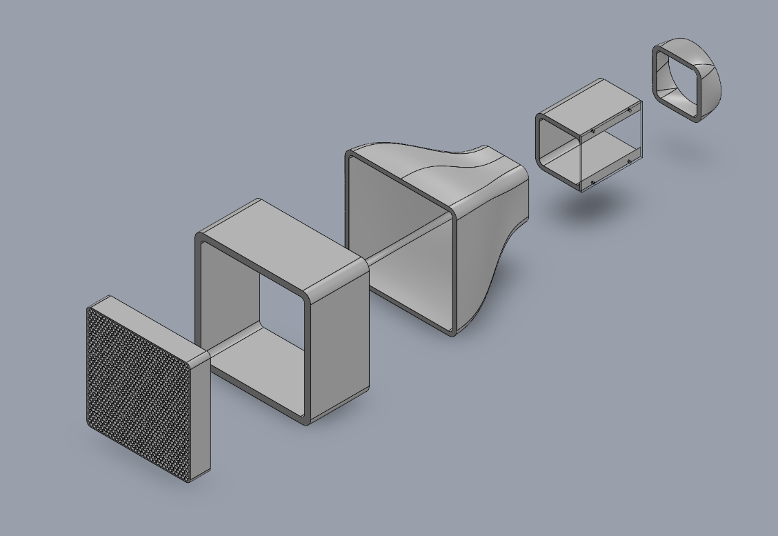
Exploded View
Design & Engineering
Design Constraints
Design was mainly limited by a 256mmx256mmx256mm build volume of 3D Printer.
This was overcome by designing the largest part, the honeycomb intake (pictured far left), to utilise the full build aera. This allows the intake to avoid connection defects and maintain smooth airflow.
This also means that all downstream components can be printed whole, as the cross section will be within the printer bed.
Contraction Cone
The intake is connected to a 6:1 ratio polynomial contraction cone modelled using the following equation:
The 1:6 ratio was chosen with reference to literature. The recomendation was between 1:4 and 1:9. 1:6 provided the largest increase in airspeed while maintaining a useable size od test section.
The length was set by Morel’s recomendation.
Morel’s recomendation: Contraction cone length = inlet side length
Test Section
The test section will feature an acryllic window to visualise flow from tufts on the specimen. The length was selected to be 150mm (1.5x the test section hydraullic diameter) in accordance with literature.
Fan/Fan Adapter
The test section then leads to a fan adapter to smooth airflow before reaching the fan.
Calculation require a fan that produces 362Pa of dynamic pressure. Fans matching this spec are hard to procure so we plan to use 2 contra-rotating server fans to meet this criteria.
A diffuser was not used as fan aera and test section area are almost identical.
Current Tasks
Connections
Currently implementing the connection mechanism to join components. Preliminary designs use M4 screws and nuts using flange connections. This is done to keep costs down and provide a simple and universal solution.
Force Measurement
A 3D printed flexure is being developed to transmit drag and lift forces to the load cells.
Load cells have been procured (100g and 500g models). The electronic circuit and logic systems are being developed to read and record load cell output voltages by my teammate.
Technical Specifications & Results
| Parameter | Target Value | Achieved Value | Status |
|---|---|---|---|
| Test Section Dimensions | 100 x 100 mm | --- | --- |
| Airflow Velocity | 15 m/s | --- | --- |
| Camber Deflection | 12 degrees | ---- | --- |