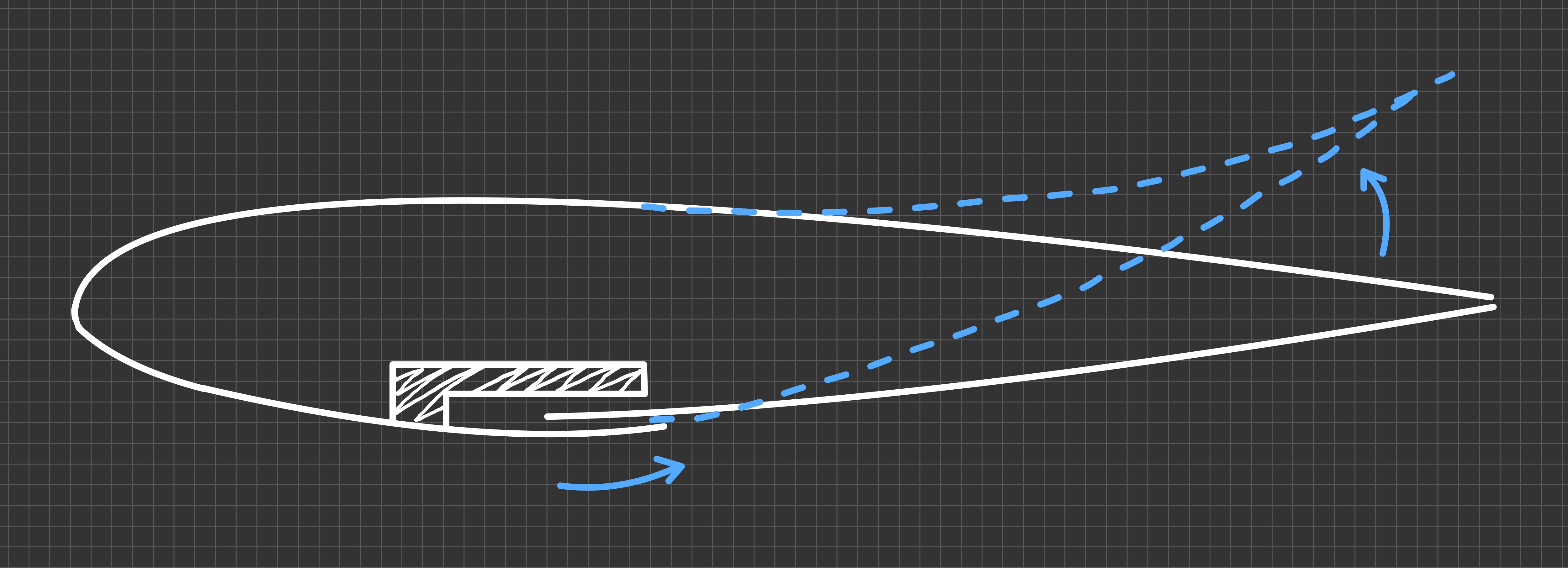
KINCS Design schematic
Project Overview
The goal of this project was to design an active morphing aerofoil which uses a compliant-mechanism to control the camber of a wing to provide aileron/elevator control. A KINCS framework (cross section pictured left) was used over a rib and skin approach so that the entire structure could be manufactured as one piece and less delicate.
Project Objectives
-
Deflection: Match traditional hinged aileron/elevator designs at 20deg deflection.
-
Actuation: Develop an internal actuation mechanism to drive the camber deflection with an ESP32 and C++ code.
-
Monolith Structure: Design the enitre aerofoil as one part to reduce moving parts and complexity.
Design & Engineering
Constraints
Design was largely limited by FDM manufacturing and material properties of the filament used.
PETG was chosen over traditional PLA filament due to it’s greater ductility.
The compliant section was printed with a wall thickness of 0.8mm, only steps of 0.4mm are available, as a balance between strength and flexibility.
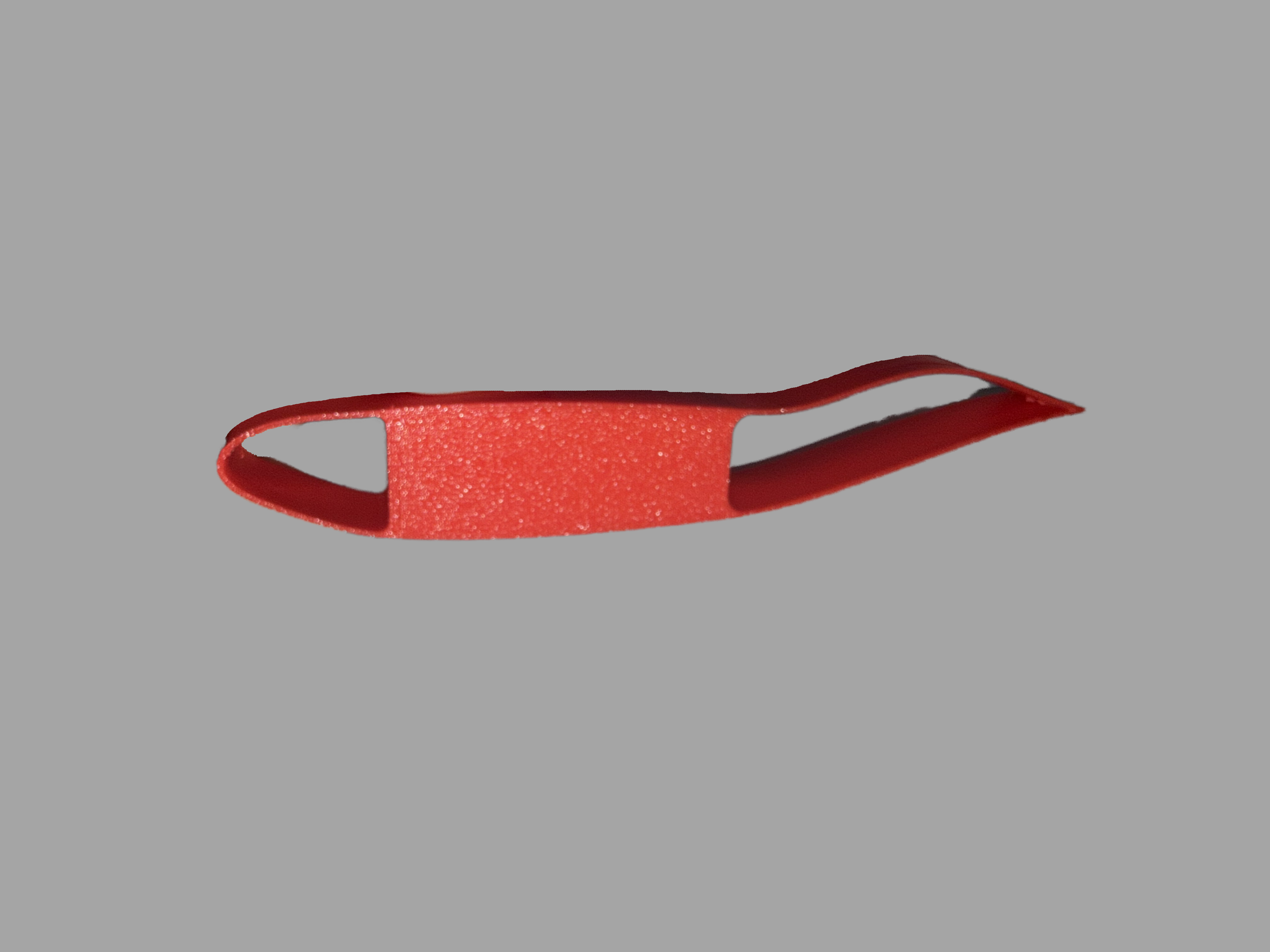
Initial Design (under buckling)
Version One
The first prototype (Pictured left) was successful in demonstrating the ability of the aerofoil to bend, however it lacked a relief cut on the surface and any bending would lead to the skin buckling.
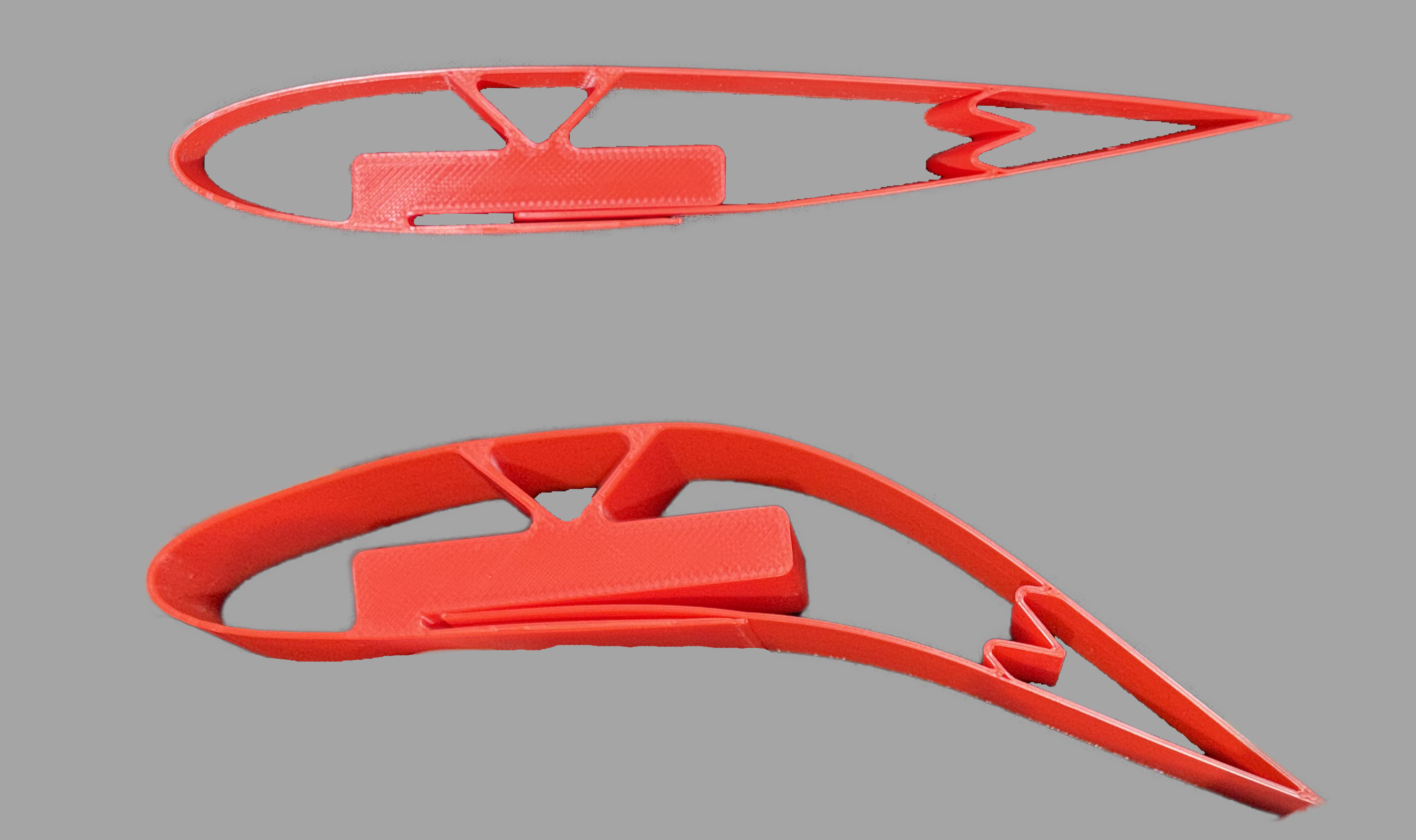
Version Two
Version Two
V2 (Pictured middle left) added a relief cut on the lower section of the aerofoil. This allowed for the top section to deflect without buckling. Weight was also removed from the centre to reduce weight.
A spring mechanism was also added in the trailing edge to ensure that the two surfaces remain constrained. This maintains a constant thickness of the aerofoil during bending.
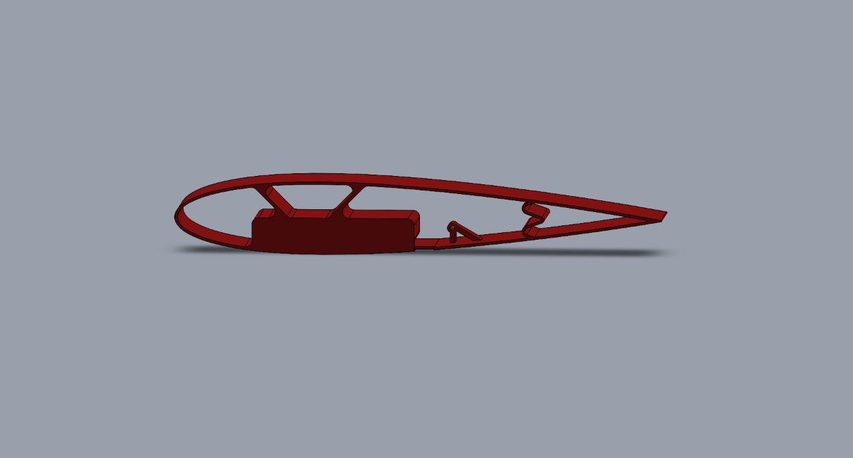
Version Three (render)
Version Three
V3 (Pictured middle left) removed further material and increased the spacing of support ribs to distribute loads evenly along top surface.
The bottom surface section was connnected to the main block to reduce undesired deflection.
An triangular anchor point was added to attach metal wire to be driven by an external servo.
The spring was reworked to remove a sharp bend at its centre.
Next Steps
Servo Mounting
Currently working on V4 which will house a MG90S servo within the aerofoil. This involves reworking the central block to increase clearence and incoorperate mounting points for the servo motor screws.
A rack-and-pinion system is also being considered as an alternative to actuate the camber deflection.
CFD Simulations
Conducting Ansys Fluent simulations to observe aerodynamic improvements over traditional, hinged trailing edge control surfaces.
Technical Specifications & Results
| Parameter | Target Value | Achieved Value | Status |
|---|---|---|---|
| Camber Deflection | 20° | 30° | Success |
| L/D ratio improvement | 10% | --- | Awaiting results |